
This is part one in a Cinematic/Freestyle FPV build video series built on the 7″ BangGod frame from Catalyst Machineworks. All build selections were made following extensive research, all parts were purchased personally with no influence by sponsors. My comments and feedback are my opinion alone. As you continue through this series, I welcome your feedback and experience based on my selection of components. Let’s get started.
Below are parts list and respective sites used (no sponsor relationships)
- BangGod 7″ Frame
- BangGod 7″ Rear Bracer
- BangGod FPV Arm Bumpers (very difficult fitment)
- Super G Battery Pad
- Caddx HD Micro Air Unit (12cm cable)
If you prefer to follow this build in a video format follow the following link to the video on ThrownException.com’s YouTube Channel.
When I originally started documenting the build I neglected to consider the many adjustments I would make upon completion. In the interest of sharing those changes as you move through this series I will devote time at the end of each video to share my observations and specific changes.

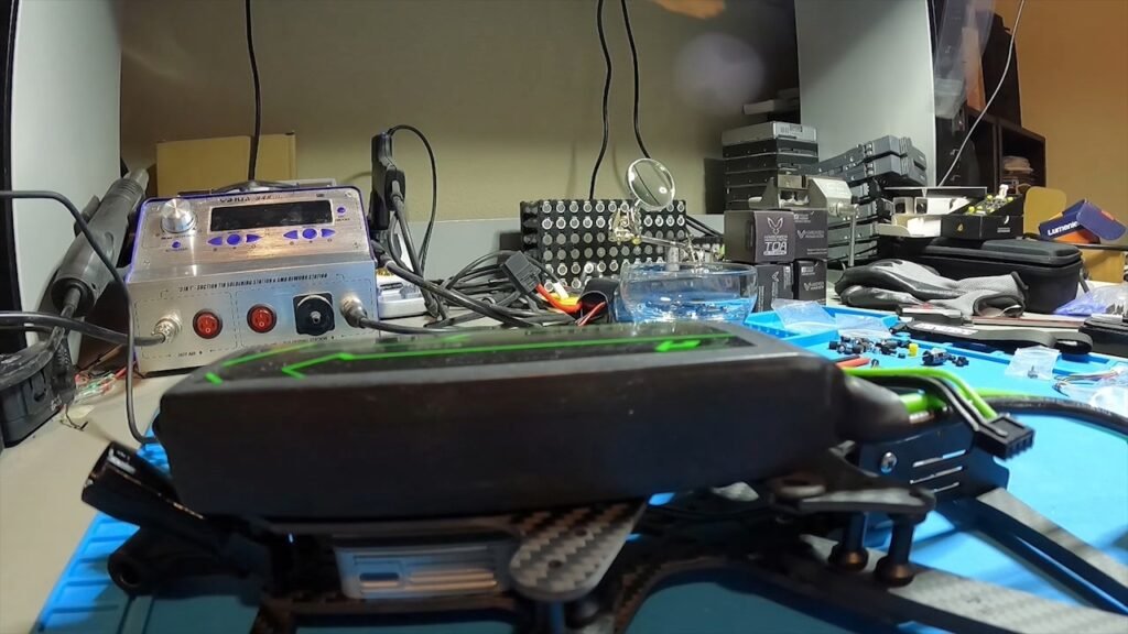
We will begin with the Frame specifications. As I stated my intent is to build a Long Range Cinematic FPV capable of Freestyle. While the Catalyst Machineworks BangGod series comes in 3, 5, 6 and 7 inch options; I selected 7″ seeking maximum stability and carrying capacity for extended flight time. The frame cost at the time of my build was $124 and that was before the addition of the $12 rear brace. If you are interested in Freestyle solely you will likely avoid this addition to minimize overall weight but for me stability and strength were key. While the price point is by most probably high the overall construction is exceptional.

The frame composition is a Twill weave 3K Matte Carbon Fiber. To promote strength where is is most needed the X frame arms and front brace are both 5mm thick, while the rear brace is 4mm thick. The bottom Carbon Fiber base is 3mm thick while the less critical top plate is 2.5mm thick. Fully assembled the frame dimensions are approximately 215mm brace to brace in length, 290mm wide and 33mm high from bottom to top plate and 40mm high on the forward camera frame. The arms measure 15mm wide and from the base they extend approximately 117mm outward offering enough distance to avoid impeding your camera view. The rear arms can be attached to either the bottom plate for Cinematic stability or to the top plate for those seeking a Freestyle or more racing centric configuration.
The BangGod 7 inch frame is compatible with 22xx, 23xx, 24xx, 25xx, 26xx and 28xx motors. The top mounting lipos are compatible with 3/4/5/6 and 8s batteries. Even with the addition of a Hero 9 camera a generous amount of space remains for a large battery installation. The maximum prop size is 7.1 inches but your selection of battery will likely determine the ideal choice. The frame offers a very roomy 22mm of space between the top and bottom plates sandwiching either a 20mm or 30.5mm Flight controller and ESC. Because of the generous space a FC/ESC stack comfortably fit inside. Additionally the large frame sports a second 20mm and 30.5mm mount option in the rear of the craft. Seeking to capitalize on maximum capabilities I opted for the 30.5mm stack options and used the rear mounting area for my FPV camera housing.

A complete package of assembly parts are provided to tackle nearly any configuration you are seeking to build. For the 7 inch frame each arms has 3 aluminum standoffs attached to the top and bottom plates for support. While assembling the frame you will note some M3 screws are silver while others have a blue tint to them. The silver screws are stainless steel rated at 70,000psi while the blue are high quality steel screws rated at 170,000psi. The placement of the high strength screws are a critical component of the outstanding strength and resilience this frame possess. For convenience each arm can be removed with only 2 screws however the precision cut parts leave no room for slop on the assembled aircraft.
The forward mounted camera housing at the nose of the craft offers numerous options for mounting both FPV and cinematic cameras. Because of the generous 7 inch footprint it supports nearly all Micro/Mini and Full sized cameras. Screw options are included within the package to mount many of the common camera choices to the frame. A special TPU camera mount standoff is included with recessed cable routes allowing for top and bottom cable paths. The TPU is attached to the frame and camera housing by four #4 1/2 inch sheet metal screws. The camera plates support an FPV camera capable of 0-75 degree mounting angles while the included knurled aluminum post on the back of the camera housing allowing easy attachment of an HD camera capable of 20-50 degree ranges.
Now that we have covered frame specifications, its time to discuss frame fabrication. One of the best resources you will find is the Catalyst Machineworks tutorial video linked on the product page. I will include links to the 7 inch product page but please note that the fabrication is relatively identical regardless of the frame size. I will touch on the steps involved but it is important to note that my intent is not to simply replicate an already outstanding tutorial but rather to provide you with feedback, clarification or advice based on my build experience. Ultimately, my mistakes or challenges will hopefully help you to be more successful in your project.

We begin by organizing the carbon fiber pieces for assembly. Starting with the 8 M3 12mm blue screws we will affix 3mm base and 5mm arms. You will notice that the screw fitting is quite snug, this is by design to avoid any movement on the frame. After installing all 8 screws we retrieve the black M3 flanged 17mm standoffs. Each arm on the 7 inch series will accommodate three standoffs, for now we will begin with the two. On the smaller BangGod models a total of 2 are used per arm. Repeat this process for the remaining 3 arms. As you attach all components you may opt for thread lock to ensure vibration does not cause the components to come loose. This is a personal choice.

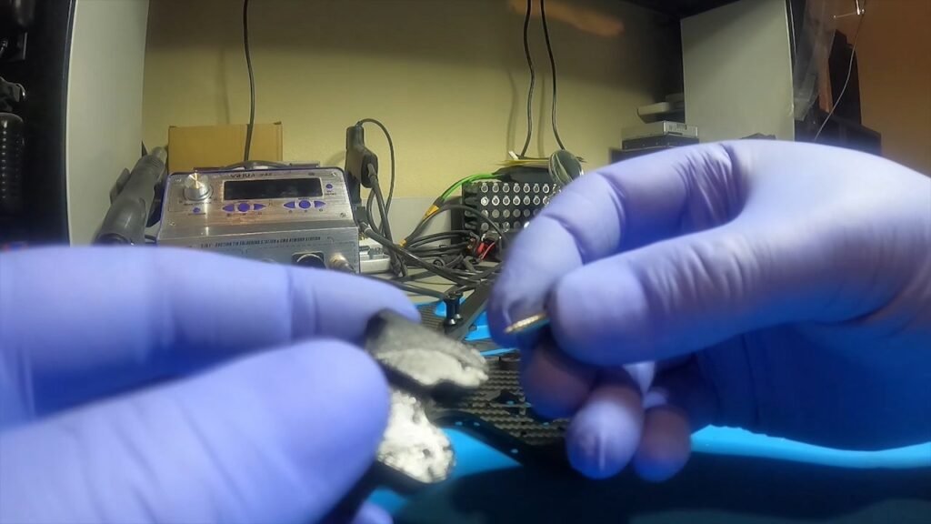
After installing the 8 M3 screws we will take 8 flanged standoffs and secure the arms to the base. Next we will attached the 22mm long black aluminum knurled standoffs to the rear of the body using the silver M3 8mm screws to secure them in place. Afterward retrieve the TPM nose and attach it to the front of the base using 2 #4 1/2 inch long sheet metal screws. Pay close attention to how you attach the TPM bulkhead as attaching it in reverse will result in your inability to properly fit the front brace to the motor mount holes. Speaking from my personal experience, no amount of adjustment will compensate for that mistake.
You will want to place the wide portion on top with the flat surface facing forward and the rounded side facing back. You will notice in the upcoming video I neglected to catch this until the end so disregard my TPM install orientation.

Additionally, because the FPV camera cable is routed either above or below the TPM if you choose to route it under for what I considered a cleaner install, you will need to attach your FPV early in the frame fabrication. I selected the Caddx HD Micro Air Unit. The stock cable is too short to support the length required for rear antennas and the forward FPV nose mount. The standard cable lengths are 8, 10 and 12cm lengths. In my experience the more difficult to find 12 cm length is ideal.

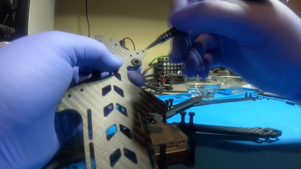
Next we will assemble the front FPV nose assembly. Grabbing the two side mounted carbon fiber plates, ensure the hooks are facing down and back. This will accommodate the front brace sliding into the grooves for significantly improved frame stability. Using 2 #4 1/2 inch long sheet metal screws on each plate you will screw them into the sides of the TPM nose. Tighten them enough that it feels secure and then turn a small bit more. Do not tighten so much as to strip out the TPM material and prevent proper attachment.

The next task is to prepare the FC/ESC stack for install. As noted the frame accommodates both 20mm and 30.5mm units. I selected 30.5mm and chose a SpeedyBee stack solution for capabilities but with the 22mm accommodations between the top and bottom plate your choices are endless. An All-In-One will fit easily leaving plenty of space for other options. If you prefer rubber shock absorbers on your components the space fully allows that option. I would note that the SpeedyBee implemented shock absorbers were significantly thick and resulted in a tight fit that warranted more creative choices. Remember that as the FPV camera cable must travel beneath your stack is imperative that you install standoffs to support this.

I tested rubber standoff options with the Catalyst included M3 screw components but the screw length prevented the standoffs from completely seating to the base plate. In the end I selected a combination of rubber O-rings, nylon nuts and SpeedyBee rubber shock mounts to construct my stack. While for some this might seem unorthodox I was pleased with the result. My take-away was simply that the 22mm of space offers you many solutions for the stack of your choice so be creative.
As my stack installation choices diverged from the Catalyst implementation I chose to skip details on my stack installation for this video as it really was about showcasing the frame. The Catalyst video details the stock solution but as I said your choices are endless. Looking at the top plate you will see a inset rounded cutout. This houses your battery cable and you can flip the top plate to accommodate either a left or right oriented cable install. An O-ring is included for installation. As my FPV implementation capitalizes on Cinematic supporting up to 6S battery options I made the decision early to go with an XT90 connector using a 12 gauge wire. Unfortunately the space carved out in addition to an o-ring makes for a very tight fit and did not line up well for my battery orientation. In the end I opted to not use it but for those interested in an XT60 or XT30 implementation I feel confident the space will more than suffice.
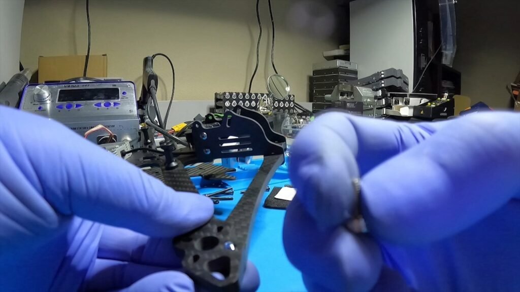
As we approach the end of our build the next step is the addition of the front and rear braces. The front brace is stock with the kit while the rear is an optional purchase. Assuming you properly orient your TPM nose housing the addition of the brace should slide in snugly to the side mounts compliments of an inset groove on the brace while mount directly to your forward motor mount holes using the M3 blue tinted 14mm screws. The remaining two screws on the front motor will be secured with two silver stainless steel M3 8mm screws. The rear arm attaches to both the rear knurled aluminum black stand offs as well as all 4 motor mount holes using the high strength blue screws for added strength.
As you will note in the video, my reverse install of the TPM did not allow proper alignment to the front motor mount. Additionally, as I followed the Catalyst video closely (though not closely enough to avoid my mistake with the TPM) the model they demo’d was a smaller frame. The 7 inch BangGod frame uses 3 black aluminum flanged standoffs. I would later catch that oversight.
Another area of consideration pertains to your choice for Cinematic camera. As I selected the GoPro Hero 9, the included black aluminum cylinder is installed at the aft section of the nose using two M3 8mm stainless steel screws. As you see in this video it is the mount point for the 3D printed GoPro housing and it slips through the mount to attach it to the frame The front of the printed mount attaches to an optional camera kit that allows for camera angle adjustments ranging from 0 to 75 degrees with two choices of attachments.

The final component install is the carbon fiber top plate. You will notice it fits in the nose housing is extremely snug forcing you to slide it from the rear forward into place. On the 7 inch frame you will need 12 blue tinted M3 8mm screws. Each of these will thread into the black aluminum flanged standoffs providing the maximum frame strength possible. You will then insert 2 silver stainless steel M3 8mm screws to the rear of the top plate while the remaining two #4 1/2 inch sheet metal screws will attach to the top of the TPM bulkhead.
As I mentioned at the beginning of the video my intent is to have you leverage my failures for your success. In doing so probably the most important part of this video will be my lessons learned. We already discussed the correct placement for the TPU as well as the use of 3 flanged standoffs on each arm for the 7 inch. Some other speed bumps encountered included the insertion of a rear motor spacers to remove the gap between the arm and the rear bracer. These must be inserted prior to installing the rear motor mount screws.

Another observation included the generous battery space afforded by the 7 inch top frame. I tested the fitment of both a 3S 4000mah battery as well as a much more hefty 6S 4500mah battery. In both cases the fitment was tight when considering the inclusion of the GoPro Hero 9 camera but honestly how many frames offer the ability to support that size battery? For me it was simply about options and intent.

Finally, to protect my investment choosing the installation of arm bumpers from the Catalyst site seemed prudent (though painful to install). The inclusion of thread lock, especially on those connections sustaining the greatest vibration offered some peace of mind. My last modification targeted a potential puncture of the battery from the upraised high strength screws attached to the flanged standoffs. I installed a Super G battery pad, cut to best fit the top plate and protect the battery.
This is Kevin from ThrowException.com, thank you for taking time to watch this video and please join us for Part 2 of our Cinematic Long Range FPV build where we discuss the Flight Controller and ESC. Until then, happy flying…
